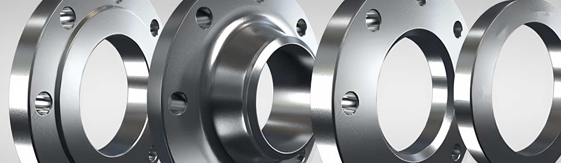
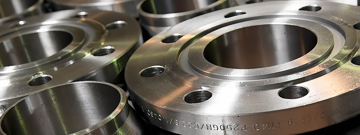
A flange is a raised collar or rim attached to another component. It helps to join two elements together, especially for pipes and vessels. Moreover, these permit sealed connections through bolting and welding to provide safety from leakages.
In addition, these are designed to endure pressure, temperature, and mechanical loads. Therefore, they are widely used in oil & gas, chemical, and power generation sectors. However, they differ depending on standards including ANSI, ASME, or DIN.
This article gives a detailed analysis of flange types connection methods, and machining ways to shape them.
What Is A Flange?
Flanges are flat circular objects. These are used to join two components together. Their common uses are in pipes, valves, and machinery. Additionally, it allows for the connecting and disconnecting of components. Also, it helps create airtight seals between those components.
A flange can bear high pressure, temperature, and mechanical loads. They may have bolt holes around the perimeter for attachment to another bracket or to a receiving part. These are normally made of steel and stainless steel depending on the intended use.
How Does Flange Connection Work?
Here are the common steps in process:
1. Design
Flanges are circular plates with a flat face and bolt holes that run around their periphery. They are intended to join pipes, valves, and or other equipment securely. Moreover, their design provides correct orientation and a rigid kinematic joint. There are smooth and raised surfaces normally used to improve the sealing mechanism.
2. Bolting
Flanges are fastened by using bolts. The bolts run through the holes provided on both sides of the seals. When the bolts are tightened the two brackets come into contact with each other and squash the gasket in between. This causes a well-fitted, watertight, or air-tight seal.
3. Gaskets
To ensure no leaks between the two flanges, always insert a gasket in between. It remains flexible when screwed on and shrinks to form a compact seal. Moreover, gaskets reduce the vibrations and allow for small misalignments.
4. Pressure and Temperature Rating
Every seal connection is intended for certain pressure and temperature requirements. These factors are defined by the design and material. The flange should also be chosen correctly for the system to avoid failures since it is critical.
5. Installation
A flange connection is physically brought into line first. Then a gasket is fitted between them before they are bolted. It is a common practice that the bolts are well-tightened to achieve a good connection with no leakage. In addition, excessive or inadequate installation can lead to signs of leakage or harm to the internal surfaces.
6. Maintenance
On flange connections, it is advisable to patrol gaskets frequently for signs of wearing, rusting, or leakage. Because it’s essential for dependable connections and use under high-pressure or high-temperature systems.
Typical Types of Flanges
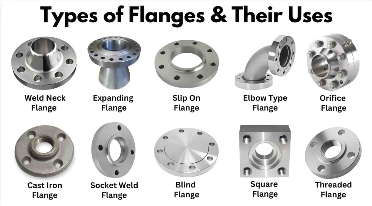
Here are some common types:
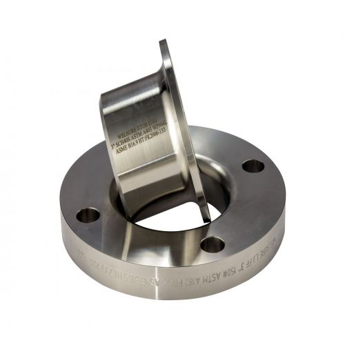
1. Weld Neck Flange
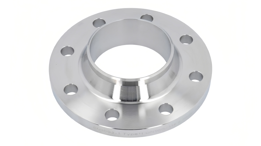
Welders attach a weld-neck flange to the pipe using a long tapered hub. These offer a firm and long-lasting joint where high pressures and temperatures are concerned. These are conical shapes, able to distribute stresses and ensure no leakage occurs.
2. Slip-On Flange
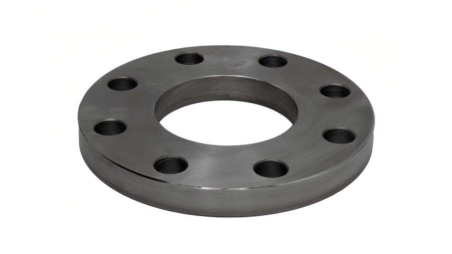
Engineers slip slip-on flanges over the pipe. Then, welded their face as well as on the pipe. These are comparatively cheaper and easier to install than other types. So, it’s recommended to use slip-on types for low-pressure systems.
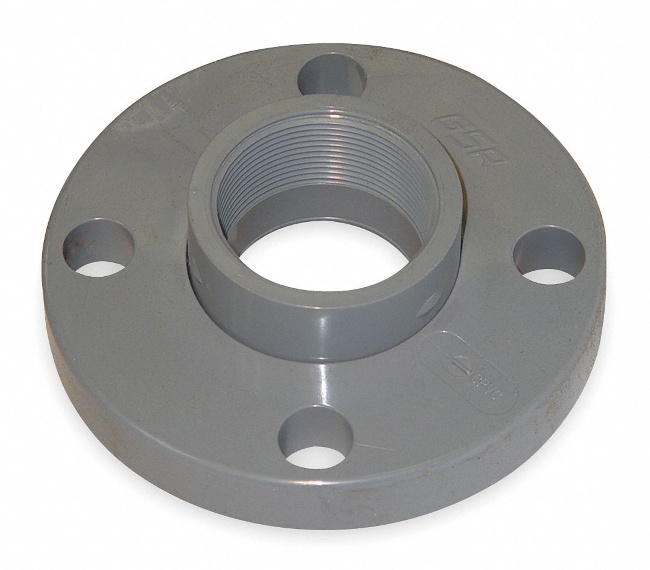
3. Threaded Flange
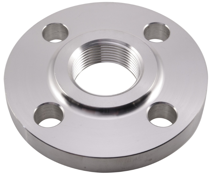
Threaded flanges have internal and external threads that match the threads of a pipe. Workers fix them by screwing, avoiding the use of welding. They are widely applicable for low-pressure systems.
4. Lap Joint Flange
Lap joint flanges are accompanied by loose backing. The pipe ends slip into the lap joint. Workers screw the lap joint flange to its backing.
5. Ring-Type Joint (RTJ) Flange
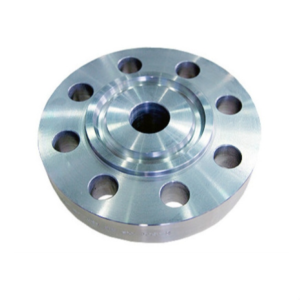
RTJ features a groove where a metal ring gasket is placed to create a high-pressure seal. They are commonly applied in the oil and gas industry, where pressures and temperatures are relatively high. Therefore, they guarantee a leakage-proof connection.
6. Orifice Flange
Orifice brackets are meant to be fitted with a flow meter or an orifice plate within pipeline systems. They have ports for determining the flow rate of fluids or gases and also hold integral pressure ports for pressure measurements.
7. Van Stone Flange
Van Stone flanges have a beveled edge which provides for a tight and leakproof interface when screwed onto another one. They are well applicable for low to medium-pressure applications and provide installation ease.
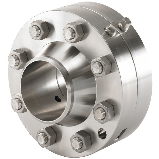
8. Tied Flange
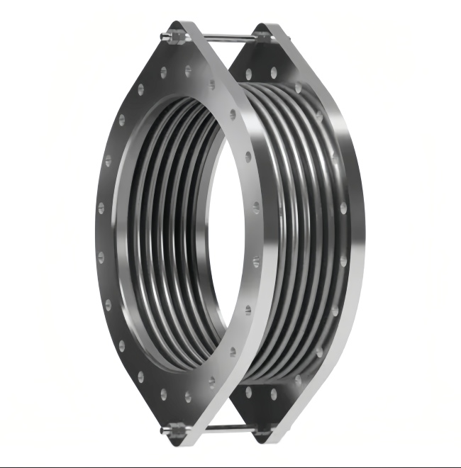
Tied flanges are used in pressure vessels that operate at high pressure and temperature. They have a tie bar that joins their outer diameter to ensure no separation under extreme pressure conditions.
Different Faces of a Flange to Connect
Here are different flange connection faces:
1. Male and Female (M&F) Faces
Designers create male and female flanges with complementary surfaces. One flange has a bulge (male) and the other has an indentation (female). It makes a perfect fit and tight connection, common in pipelines, and high mechanical applications.
2. Tongue and Groove (T&G)
Tongue and groove faces have a protruding “tongue” on one flange and a groove that matches the shape of it on the other. This design offers a better grip, and the seal is less prone to separation or leakage.
3. Flat Face with Raised Face (FF-RF)
The combined design has a flat face with a sealing area over it. It seals better and works well in systems with limited space, and special sealing. Moreover, it is simple to install, though it provides less pressure at the seal.
4. Recessed Face (RF)
The recessed face has a groove surrounding the sealing area. The groove retains the gasket. It is commonly utilized for improved sealing and fit in high-pressure applications.
5. Integral Flange (IF)
The integral flange is a pipe fitting made in one piece. Designers make the flange and the pipe simultaneously. This makes the connection easier and reduces the leakage.
Flange Dimensions and Considerations for Optimal Flange Sizes
Let’s figure out precise dimensional considerations for flanges:
1. Nominal Pipe Size (NPS)
The nominal pipe size (NPS) defines the essential dimensions of flanges. It generally from ½ inch (DN 15) to 24inchesh (DN 600). Although larger sizes are also possible. For instance, a 3-inch flange has an internal diameter of approximately 3 inches of the pipe. Thus, these should be the same size as the pipe NPS to meet the right size for the flange and the pipe.
2. Bolt Circle Diameter (BCD)
The diameter of the bolt circle depends on the flange size. For instance, for 1 NPS, BCD could be around 2.75 inches, and for 6 NPS, BCD could be around 8.50 inches.
3. Bolt Hole Size
Manufacturers usually drill bolt holes to a standard size. Normally, it is equal to the diameter of the bolt plus 1/8 of an inch. For example, a flange having 1/2-inch bolts has bolt holes measuring about 5/8 inches in diameter. The number of bolts and spacing also vary with the flange size and pressure rating.
4. Flange Face Type
- Flat Face (FF): For usage in low-pressure applications especially in regions up to 150 psi.
- Raised Face (RF): Usually applied in the middle to the high-pressure range including 600 or 1500 psi.
- Ring-Type Joint (RTJ): Used in high-pressure applications, normally in applications above 1500psi, and needs a metal gasket to make the seal leakproof.
5. Thickness (Flange Thickness)
The thickness of the flange depends on the pressure class and the material used. For example:
- The thickness of 150 lb flanges (ANSI class 150) is usually approximated to 0.25 inch for small nominal pipe sizes (NPS 1-1/2 to 2).
- Flanges of 300 lb (ANSI class 300) may have thicknesses up to 0.75 inches for NPS 6.
- Flanges whose rating is 1500 lb (ANSI class 1500) may provide thicknesses of up to 1 inch or more for sizes of 10 NPS and above.
6. Pressure Rating
Engineers rate flanges by pressure, commonly as;
- Class 150: Recommended for use at pressures up to 285 psi at 100°F.
- Class 300: Tested for pressure of up to 740 psi at the temperature of 100°F.
- Class 600: Approved for pressure of up to 1480 psi at 100°F.
- Class 1500: For Pressure use up to 3700 psi @ 100°F.
7. Gasket Compatibility
Standard gasket types include:
- Flat gaskets (rubeer or PTFE): For flat face flanges.
- Ring gaskets: For RTJ flanges.
- Spiral wound gaskets: Engineers commonly use raised face flanges at high pressures up to 3000 psi.
8. Standards and Codes
Common flange standards include:
- ASME B16.5: It ranges from flanges 1/2 inch (DN 15) to 24 inches (DN 600).
- ASME B16.47: For flanges 26 inches (DN 650) and larger.
- API 6A: Flanges for oil and gas, intended for higher pressure (up to 20,000 psi and above).
9. End Connections
- Welded: A tapered neck defines a weld neck flange. It is butt-welded to the pipe.
- Threaded: Threaded flanges are normally specified for small pipe diameters of up to 2 ½ inches and the thread sizes may vary between ½ inch to 2 ½ inches.
- Slip-On: Up to 24 inches in most cases, and then welded to the pipe.
10. Manufacturing Tolerances
The manufacturer determines the tolerances of brackets during their production according to the standard. For example, The outer diameter of a 3-inch flange may be ±1/16 inch in tolerance.
Flange Dimensions for 1/2″, 3/4″, 1″, and 1 1/4″ NB (DN15, DN20, DN25, DN32) Flanges
1/2″ NB (DN15) Flange Dimensions Table
| Pressure Rating | Flange Diameter | PCD | No. of Bolt Holes | Bolt Diameter | Hole Diameter | Raised Face Diameter | Raised Face Height |
| PN6 | 80mm | 55mm | 4 | M10 | 11mm | 40mm | 2mm |
| PN10 | 95mm | 65mm | 4 | M12 | 14mm | 45mm | 2mm |
| PN16 | 95mm | 65mm | 4 | M12 | 14mm | 45mm | 2mm |
| PN25 | 95mm | 65mm | 4 | M12 | 14mm | 45mm | 2mm |
| PN40 | 95mm | 65mm | 4 | M12 | 14mm | 45mm | 2mm |
| PN64 | 105mm | 75mm | 4 | M12 | 14mm | 45mm | 2mm |
| Table D | 3 3/4″ (95mm) | 2 5/8″ (67mm) | 4 | 1/2″ (13mm) | 9/16″ (14mm) | ||
| Table E | 3 3/4″ (95mm) | 2 5/8″ (67mm) | 4 | 1/2″ (13mm) | 9/16″ (14mm) | ||
| Table F | 3 3/4″ (95mm) | 2 5/8″ (67mm) | 4 | 1/2″ (13mm) | 9/16″ (14mm) | ||
| Table H | 4 1/2″ (114mm) | 3 1/4″ (83mm) | 4 | 5/8″ (16mm) | 11/16″ (17mm) | 2 1/4″ (57mm) | 1/16″ (2mm) |
| ANSI 125/150 | 3 1/2″ (89mm) | 2 3/8″ (60mm) | 4 | 1/2″ (13mm) | 5/8″ (16mm) | 1 3/8″ (35mm) | 1/16″ (2mm) |
| ANSI 300 | 3 3/4″ (95mm) | 2 5/8″ (67mm) | 4 | 1/2″ (13mm) | 5/8″ (16mm) | 1 3/8″ (35mm) | 1/16″ (2mm) |
3/4″ NB (DN20) Flange Dimensions Table
| Pressure Rating | Flange Diameter | PCD | No. of Bolt Holes | Bolt Diameter | Hole Diameter | Raised Face Diameter | Raised Face Height |
| PN6 | 90mm | 65mm | 4 | M10 | 11mm | 50mm | 2mm |
| PN10 | 105mm | 75mm | 4 | M12 | 14mm | 58mm | 2mm |
| PN16 | 105mm | 75mm | 4 | M12 | 14mm | 58mm | 2mm |
| PN25 | 105mm | 75mm | 4 | M12 | 14mm | 58mm | 2mm |
| PN40 | 105mm | 75mm | 4 | M12 | 14mm | 58mm | 2mm |
| PN64 | 130mm | 90mm | 4 | M16 | 18mm | 58mm | 2mm |
| Table D | 4″ (102mm) | 2 7/8″ (73mm) | 4 | 1/2″ (13mm) | 9/16″ (14mm) | ||
| Table E | 4″ (102mm) | 2 7/8″ (73mm) | 4 | 1/2″ (13mm) | 9/16″ (14mm) | ||
| Table F | 4″ (102mm) | 2 7/8″ (73mm) | 4 | 1/2″ (13mm) | 9/16″ (14mm) | ||
| Table H | 4 1/2″ (114mm) | 3 1/4″ (83mm) | 4 | 5/8″ (16mm) | 11/16″ (17mm) | 2 1/4″ (57mm) | 1/16″ (2mm) |
| ANSI 125/150 | 3 7/8″ (98mm) | 2 3/4″ (70mm) | 4 | 1/2″ (13mm) | 5/8″ (16mm) | 1 11/16″ (43mm) | 1/16″ (2mm) |
| ANSI 300 | 4 5/8″ (117mm) | 3 1/4″ (83mm) | 4 | 5/8″ (16mm) | 3/4″ (19mm) | 1 11/16″ (43mm) | 1/16″ (2mm) |
1″ NB (DN25) Flange Dimensions Table
| Pressure Rating | Flange Diameter | PCD | No. of Bolt Holes | Bolt Diameter | Hole Diameter | Raised Face Diameter | Raised Face Height |
| PN6 | 100mm | 75mm | 4 | M10 | 11mm | 60mm | 2mm |
| PN10 | 115mm | 85mm | 4 | M12 | 14mm | 68mm | 2mm |
| PN16 | 115mm | 85mm | 4 | M12 | 14mm | 68mm | 2mm |
| PN25 | 115mm | 85mm | 4 | M12 | 14mm | 68mm | 2mm |
| PN40 | 115mm | 85mm | 4 | M12 | 14mm | 68mm | 2mm |
| PN64 | 140mm | 100mm | 4 | M16 | 18mm | 68mm | 2mm |
| Table D | 4 1/2″ (114mm) | 3 1/4″ (83mm) | 4 | 1/2″ (13mm) | 9/16″ (14mm) | ||
| Table E | 4 1/2″ (114mm) | 3 1/4″ (83mm) | 4 | 1/2″ (13mm) | 9/16″ (14mm) | ||
| Table F | 4 3/4″ (121mm) | 3 7/16″ (87mm) | 4 | 5/8″ (16mm) | 11/16″ (17mm) | 2 1/2″ (64mm) | 1/16″ (2mm) |
| Table H | 4 3/4″ (121mm) | 3 7/16″ (87mm) | 4 | 5/8″ (16mm) | 11/16″ (17mm) | 2 ½’’
(64mm) |
Machining Techniques of Flanges
Designers can design flanges through various techniques, including;
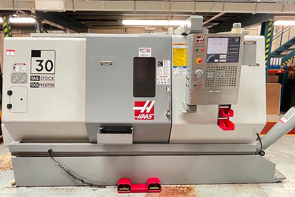
CNC Turning
CNC Turning peel material away from a workpiece by revolving it. The operation forms a cylindrical shape with a cutting tool. Moreover, this minimizes the chances of obtaining rough surfaces. The turning operation is precise and helps in creating the dimensions of the object accurately.
CNC Milling & Drilling
CNC Milling employs cutting tools that revolve around to carve off the material. It also brings about the formation of flat angular contoured, and other desired surface types. Milling is optimum for designing seal edges, and intricate shapes. In addition, CNC drilling helps to make holes in them as well.
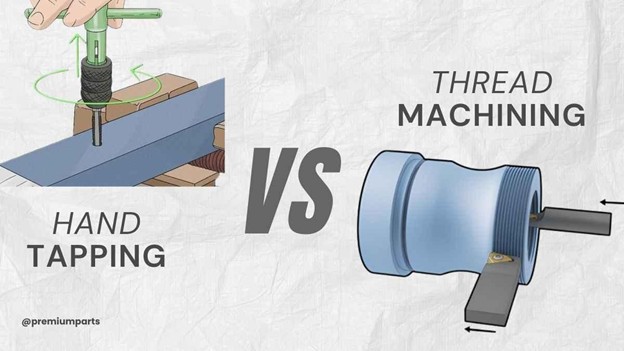
Tapping
Tapping involves cutting internal threads into the holes. It shapes the brackets ready for bolts and fasteners. In addition, the tapping operation also secures the right thread size.
CNC Grinding
Grinding involves rubbing a surface against an abrasive wheel. It offers a smooth finish to flange faces and offers a smooth finishing. Moreover, grinding helps to achieve a high accuracy level in sealing surfaces and their fitness.
Face Milling
The face milling operation also takes off material from the flange surface. It forms a plane, uniform surface to make a seal. The process provides the right gasket installation and functionality.
CNC Grooving
Grooving cuts narrow grooves into the flange. It frequently forms an area for gaskets or seals. This prevents the formation of incorrect gasket positions during operation. Furthermore, it offers a sealing surface for safe operation.
Cutting/Shearing
Manufacturers create the flange from metal profiles by cutting the shapes. Shearing requires a high force for cutting material. It puts the flange in a condition for further machining process.
Blasting
Cleaning flange surfaces using abrasives by blasting. It cleans the fluid and reduces unwanted stuff like rust. The process provides a sleek and clean-aesthetic shape. It makes the flange ready for final turning or painting.
CNC Welding
The welding process joins two or more metal parts through heat or pressure. Moreover, the operation provides the users with firm and irreversible links.
Final Summary
In industrial processes, flanges play the key role of providing an easy, reliable, and leakproof joint between pipes, valves, and other system components. The basic machining operations utilized to produce flanges, turning, milling, drilling, and welding. These are crucial elements for the production of the desired accuracy and standard quality. In addition, each face milling, slotting, counter boring, or tapping process further improves the functioning and overall performance of the flange. However, it’s advisable to select the appropriate flange dimensions, material, and manufacturing processes so that the flange complies with an engineering specification.
At Premium Parts we focus on providing quality, accuracy, and customized flanges that fit the requirements of our valued customers. Our advanced manufacturing technologies and zero tolerance for compromise on quality make us deliver flanges of optimal quality in the market. For any important pipelines or intricate equipment, you can turn to Premium Parts for highly efficient and long-lasting flanges.