Have you ever faced a condition when parts failed to join perfectly in assembly due to slight variations? Such issues lead to high-cost reworking and production delays. Conventional dimension methods fail to show precise dimensions. This results in inconsistencies in parts, impacting quality control. Because of this, manufacturers need a standardized and reliable dimensioning system to confirm accuracy.
This is where GD&T comes into play. GD&T minimizes variations by precisely showing part dimensions and constraints. Using this, engineers can make products with high consistency and accuracy. Moreover, the system also increases efficiency by minimizing rework, scrap, and inspection.
This blog covers the GD&T basics, importance, working, and essential symbols. By the end of this, you will understand how this dimensioning method increases manufacturing efficiency and precision.
What is GD&T?
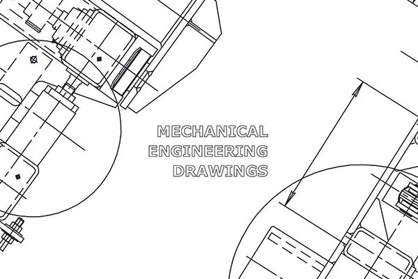
The technical drawings rely on Geometric Dimensioning and Tolerancing (GD&T) as their symbolic representation system. The language defines exact geometric restrictions to specify part features. GD&T functions as a current method to control both shapes and their positions, including orientation and runout. This system produces parts with exact dimensions, especially when the assembly structure is complex.
Our system standards help define what errors are allowed. Engineers use GD&T to define what parts must do instead of just providing their size measurements. The machinist translates symbol-based specifications into physical parts based on their understanding. Both aerospace and automotive medical companies use GD&T to maintain their production reliability. Manufacturers produce better products with fewer errors and faster production thanks to this system.
Limitations of Tolerances Before GD&T
Before GD&T, design manufacturers used conventional tolerancing systems, which proved ineffective for their work. Engineers relied on +/- tolerancing for linear dimensions until GD&T replaced it because this method did not control form orientation or position. The method of tolerancing produced parts that would not properly fit together and caused many rejects.
The problem of tolerance stacking became worse due to small dimensional variations gradually producing major assembly errors. The conventional standard tolerancing methods would not work for aerospace and medical device components because they did not handle complex product forms. So, the quality inspectors faced communication issues because they lacked common production rules.
GD&T standards, including ASME Y14.5 and ISO 1101, helped industries resolve their existing problems. These frameworks created a standardized symbol system to guide how parts should vary dimensionally, which helped lower mistakes and made production more effective.
GD&T helped manufacturers achieve higher product quality by reducing waste and streamlining their production processes, which led to the development of modern precision engineering.
What Is The Importance of GD&T in Precision Manufacturing?
Improving Assembly Fit and Functionality
When manufacturers use GD&T, their parts fit together seamlessly during assembly. When manufacturers apply GD&T, they can achieve perfect part alignment and decrease the number of assembly breakdowns. Engineers can produce parts more precisely by controlling shape features, which leads to fewer product failures and enhanced accuracy.
Reducing Manufacturing Costs
GD&T brings down manufacturing expenses as one of its key advantages. When GD&T is used, parts fail less often, production waste decreases, plus there is less work to redo. Machinists produce parts with higher accuracy because strict tolerance limits help them reduce mistakes and do their work faster.
Bridging Between Design & Product
GD&T creates a common approach for engineers to explain technical drawings clearly. The specifications help all staff members, including engineers, machinists, and quality control experts, to read data with complete understanding. The language develops better production processes and reduces mistakes to make operations more effective.
Consistency in Quality Control
GD&T serves as the main quality control standard that keeps production results consistent through multiple production operations. Manufacturers can meet their industry requirements through GD&T to make dependable, high-quality products. People working in aerospace and automotive sectors plus medical businesses need to focus on precision because it stays a fundamental requirement.
How does GD&T work?
The set of standardized symbols with tolerance zones enables GD&T to function. The standardized symbols establish what constitutes an acceptable variation in the features of a part. Engineers employ feature control frames as a tool for precise requirement communication. The geometric symbol and datum references, along with tolerance values, appear in each frame.
The tolerance system ensures that surfaces align perfectly at right angles through perpendicularity specifications. Position tolerance maintains the exact locations of holes for successful assembly requirements.
The application of datums serves an essential function in GD&T because they establish reference positions for measurement. These requirements enable the proper alignment of all features to preserve part structural integrity. The proper implementation of GD&T leads to easier inspections and increased precision during manufacturing operations. Machinists need to understand GD&T controls to develop high-quality functional components.
Understanding GD&T Controls for Precision Machining
GD&T ensures precise manufacturing of parts through its specification of geometric constraints. Engineers, together with machinists and manufacturers, depend on GD&T to enhance product assembly capabilities and operational function as well as performance levels. The following section examines five core GD&T control types alongside their subcategories, which describe their function in precision CNC machining operations.
Form Controls
The shape of a part remains under form control parameters that ignore dimensions and placement. The production process maintains consistent dimensions, which leads to better assembly quality and improved system performance.
– Straightness
The definition of straightness establishes a specific dimensional area for both surfaces and axes to stay within. The technical standard provides smooth motion and proper alignment for shafts, rails, and linear guides. Mechanical systems experience excessive wear together with friction and misalignment when deviations occur.
– Flatness
A flat surface exists between two parallel planes according to the flatness specification. Gasket surfaces, together with mounting plates and structural panels, require this specification. When surfaces are not flat, it causes uneven contact that negatively impacts both sealing and load distribution in assembled components.
– Circularity
A cylindrical or spherical part maintains equidistance to its central axis due to circularity, which refers to roundness. Bearings and gears, together with rotating components, require this quality to operate correctly. The resulting deviations produce irregular motion together with vibrations and a shortened component lifespan.
– Cylindricity
Cylindricity takes circularity beyond single cross-sections by making the entire cylindrical surface maintain a uniform diameter with a straight axis. Hydraulic pistons, together with shafts and roller bearings, require this dimensional quality for proper operation. The mechanical performance of a system deteriorates when cylindricity lacks consistency because this leads to unsuitable fits, leakages, and reduced operational efficiency.
Profile Controls
The profile control system maintains intricate shapes by ensuring they meet their exact design requirements. These geometric specifications find extensive usage in aerospace fields and automotive production, as well as mold production.
– Profile of a Line
A defined path determines how cross-sectional shapes vary when using line profile control. The profile of a line serves as an essential requirement for aerodynamic surfaces along with turbine blades and medical implants. Physical irregularities create adverse effects on fluid movement and surface behavior as well as functional output.
– Profile of a Surface
The profile of a surface implements line control methods to maintain accurate dimensions across entire three-dimensional components. The manufacturing process employs this method for producing complex castings and injection molds along with optical components. The performance, along with the appearance and assembly capability of products, become compromised when deviations occur.
Orientation Controls
Features require orientation controls to preserve their angular positions relative to selected datums. These specifications create essential conditions required to achieve the proper alignment of assemblies.
– Perpendicularity
A surface or axis must maintain a right angle position against the datum to qualify as perpendicular. This component requires proper attention in mounting surfaces along with fastener holes and support structures. Structures become weak and develop uneven loading conditions when the perpendicularity between elements fails.
– Parallelism
The application of parallelism maintains a constant distance between two surfaces throughout their entire length. The manufacturing process uses this technique in guide rails as well as linear actuators and precision molds. The occurrence of deviations leads to binding effects and produces uneven wear patterns, which affect operational efficiency.
– Angularity
A feature requires angularity when it must maintain a certain orientation that deviates from 90 degrees. The application of angularity controls is crucial for chamfers as well as inclined supports and pipe fittings. The flow path force distribution and geometric compatibility become negatively affected by angularity that is not consistent.
Location Controls
The exact positioning of features against a datum is defined by location controls. These constraints stop alignment problems that lead to improper assembly and operational failure.
– Position
When using position control, a hole, pin, or feature will precisely occupy its intended position. The positioning of hole patterns along with dowel placements and fastening systems requires it to be critical. When parts are not properly positioned, they become misaligned, which results in weak joint assembly failures.
– Concentricity
All circular features need to align their axes through concentricity. The manufacturing industry commonly utilizes this method for producing shafts and couplings, as well as bearing assemblies. Rotating systems experience excessive wear and vibrations, together with performance inefficiencies when misalignment occurs.
– Symmetry
The distribution of features throughout a central plane remains balanced by symmetry. The proper functioning of balanced components, including gears, pistons, and casings, depends on this requirement. Deviation causes both performance degradation through unbalanced stress and performance reduction through uneven distribution of stress.
Runout Controls
The operation of rotating components remains uniform through runout controls, which also prevent equipment from developing operational imbalances.
– Circular Runout
The circular runout measurement determines how much a rotating part deviates from its axis when its surface is evaluated. The proper functioning of wheels and pulleys, as well as rotating seals, depends on runout control. Mechanical failures, inefficient motion, and wobbling occur when runout exceeds acceptable limits.
– Total Runout
Entire surfaces should receive circular runout treatment to establish rotational consistency throughout their full rotation. Technology plays an essential role in high-speed machinery turbines and automotive axles. Vibration, together with noise and premature component failure, emerges when total runout reaches poor levels.
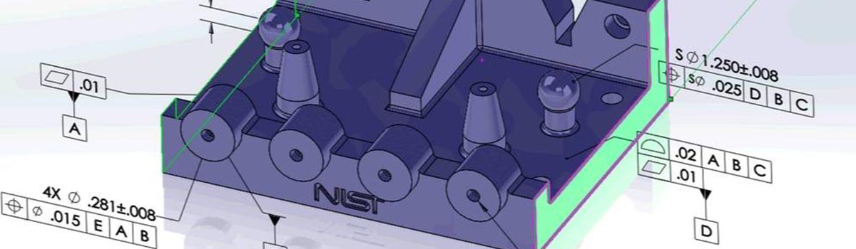
What Is The Feature Control Frame In GD&T?
The Feature Control Frame (FCF) functions as the fundamental GD&T element because it defines all geometric tolerances for specific features. Engineers implement this formal notation as a method to specify part requirements. The FCF includes three essential components that encompass a geometric characteristic symbol together with a tolerance value and datum references. The geometric symbol determines which type of control will be used, such as flatness or position. The tolerance value dictates the acceptable variation in millimeters or inches. The fixed coordinate system for measurement is established through datum references.
The functional success of manufacturers depends on FCF because it removes technical drawing confusion to ensure parts fulfill their design function. The frame serves as a mechanism to guarantee correct alignment and operational precision of all features. The aerospace industry, together with the automotive and medical sectors, depend on FCF as their primary method for maintaining precise manufacturing tolerances. When FCF is used correctly, it leads to both faster inspections and a reduced need for additional work on completed products. Engineers produce highly precise and reliable components through the implementation of a well-defined feature control frame.
Conclusion
For any part, accuracy and quality define manufacturing success. GD&T confirms parts lift, minimizes inspection time, improves functioning, and works flawlessly. Manufacturers prefer this for better communication, efficiency, and negligible errors across production and design. Whether you’re making small assembly parts or high-tech aerospace components, GD&T helps you achieve the required specifications.
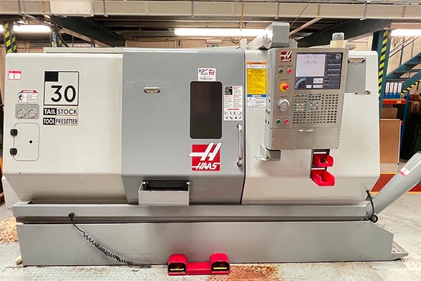
Machining isn’t something that you can give to just any person. You need trusted persons with the required skills and knowledge. This is why PremiumParts is the best option for you.
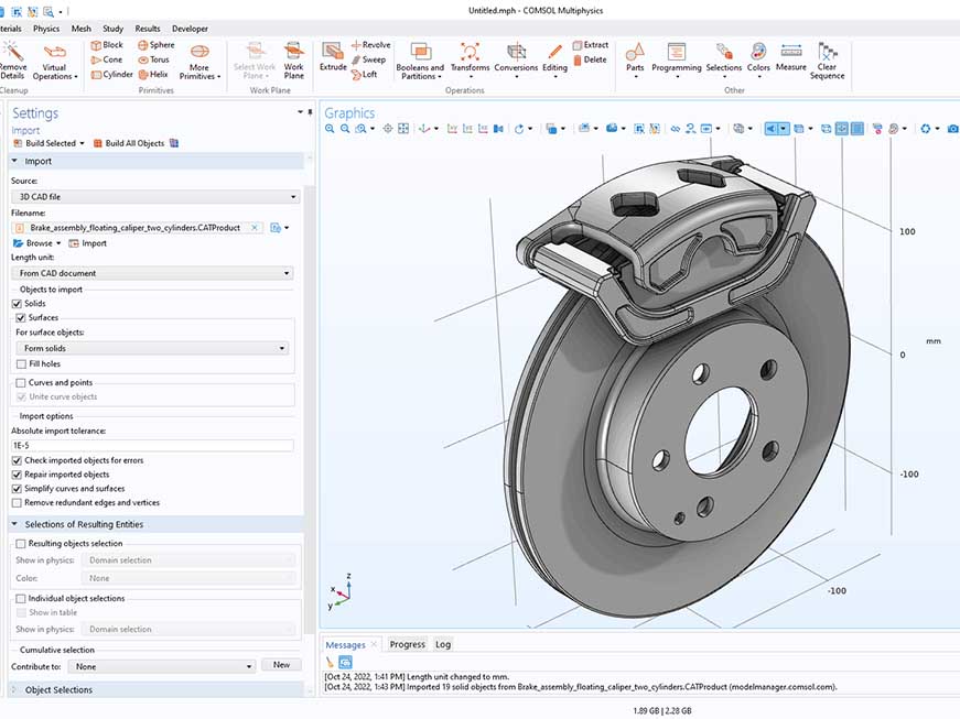
Our high-tech technologies and expert team will meet your high-tolerance requirements. We also offer overall tolerance inspection before handing over to customers. Upload your CAD file of the required part and get instant quoting. At PremiumPart, we understand that you need the best service at a reasonable price. This is exactly what we offer.
FAQ’s
Q1: What is GD&T, and what is its importance?
Geometrical Dimensions & Tolerancing defines the geometric tolerance, confirming the accurate manufacturing and assembly fit.
Q2: How does GD&T increase the manufacturability of products?
GD&T increases manufacturability by reducing waste and errors and confirming precision in parts quality.
Q3: What is the key difference between GD&T and traditional tolerancing?
GD&T controls the orientation, form, and position of the part. While traditional ones only control size.
Q4: Which industries prefer GD&T the most?
Main industries, including medical, aerospace, and heavy machinery industries, prefer this tolerancing method for high accuracy and efficiency.